Glen Downing’s MILW (Milwaukee Road)
and CNSM (Chicago, North Shore and Milwaukee)
November 9, 2019

by Lee Stoermer
Some bold and interesting plans are among the first things that come to
mind after speaking with the owner/builder of this HO scale model
railroad. Glenn Downing has a long and storied history with prototype
railroads that deserves another article all of its own in the future.
This history of railroads and their operations bridged from the N&W
(Norfolk and Western) to E&LS (Escanaba and Lake Superior) with
several in between. Those stories we'll have to save for another time
though as this time the story is about his model railroad.
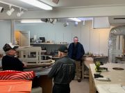
I contacted Glenn in advance of his open house to gain some insight. A
few days prior we were able to speak together over an hour-long
enjoyable phone call. That led to email exchanges about everything from
his vision to construction methods to operating scheme. His inspiration
and general theme are the 1944 era just prior to the European invasion
by the Allies. It is based on a route from Chicago following along the
North Shore towards Milwaukee then continuing to the Michigan upper
peninsula. He has significant first-hand knowledge of the area from
prior work experiences there.
This is the fourth layout Glenn has constructed. The origins of the
current layout began in 2012 with planning and construction began about
2015. The layout includes two separate railroads connected via an
interchange track in Racine, Wisconsin. Routing includes some Chicago
North Shore and Milwaukee Railroad, with somewhat parallel Milwaukee
Road trackage in that area, extends through Green Bay and Coleman with
several ag businesses, then onto Crivitz, WI via a helix. At Crivitz,
his model branches off to Marinette, WI and Menominee, MI. The main line
then continues on a helix to Pembine and then Iron Mountain and then to
Ontonagan, MI on Lake Superior, which is the northern terminus of the
model. His model serves the Green Bay area for paper mills and
associated industry.
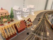
There are several key towns and scenic elements that will make it
identifiable. The route begins at the Chicago passenger terminal, runs
northward with parallel running lines of the Milwaukee and Chicago North
Shore, and ends at a paper mill. Routes continue into staging that
represent rail lines in further directions from both ends of the layout.
South staging for beyond Chicago allows Glenn some freedom to include
some big-name passenger trains which he has more than a passing interest
in.
The layout is housed in a 16 x 26 room. The track plan concept was drawn
out and developed on a series of hand drawn 1"-1' drawings done for
basic coarse design to fit that dedicated space. Sidings and mainline
tracks were drawn in for the base design plan to see what could fit in
and general placement. The benchwork was made to follow these general
track needs and final trackwork location was dictated as actual
trackwork was being put in place.
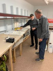
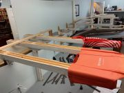
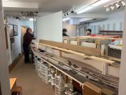
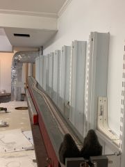
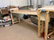
His layout is built using a different version of framework. While
similar to typical base framework we are familiar with, he has taken a
few liberties and expounded upon them for excellent results. Framework
is made from 1x2 and 1x3 lumber. While this is common in L-girder, that
type isn't used. A better description is the photo included in the
article that shows the benchwork much better. Even better yet is being
able to visit the layout, view it, ask a couple questions and then
realize how it all goes together. This is a definite benefit to visiting
in person as opposed to reading an article and a few photos. While this
may seem like very small unstable lumber, the layout framework is quite
sturdy and strong. It is more of a sandwich of the different sizes that
then has a common web section. Particularly the leg construction makes
it a convenient method of attaching bracing angles. The peninsula
strengthens itself in using a divider wall made of a serpentine
construction method developed by Tom Jefferson. Color photo cut outs
will be used on the painted Masonite or sheet styrene used for the
backdrop.
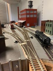
Track is a mix of Atlas, Micro Engineering and Peco code 83 and 70,
using the differing rail sizes where proper. Code 100 rail is used in
hidden trackage areas. Track is secured to roadbed material of cork or
homasote. Mainline track currently runs about 100 feet, with an eventual
finished main and branchline track that will total around 350 feet.
Yards and sidings will add about another 200 feet of track. Glenn
prefers hand thrown turnouts, no powered switch motors, so leans towards
the use of Peco spring motion turnouts and over spring controls. Doing
so keeps the train's operation crew nearer their train, keeping
operations truer to ground operating switch crews.
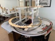
A helix in the center turnback loop uses a Y track to connect a couple
upper levels. This area is in the beginning phase of construction. This
will use a sandwich of thinner material, making a lamination of three
layers of three-ply plywood to increase strength, and reduce twisting
that is commonly found when using a single layer material. His layout is
split between five levels, although they aren't all visible at the same
time. Town areas were basically level while utilizing a longer incline
hidden from immediate view. One of these was to gain the needed height
from the lowest level staging yard to the first main level of
operations, as well as between some towns.
Operations goal is about five trains operating at any one time on the
MILW, and three trains (two passenger and one freight) on the North
Shore. Around ten operators would be the maximum that could be
comfortably engaged in the space allowed. Thoughts are leaning towards
timetable and train orders. Glenn is very familiar with using
stringlines to determine operational capabilities and time frame. These
coupled with single use waybills using AAR car types on waybills will be
the basis for bringing the layout to life. By using a 1943 industry
list, the waybills will have actual destinations that coincide with
routings.
Digitrax DCC wireless is the control system of choice for the layout,
with the eventual conversion of locomotives to sound decoders being a
standard. Kadee couplers are used throughout on all rolling stock for
their strength, ensuring operational reliability, by replacing any
plastic couplers. Trains are expected to top out at around 15 cars in
length. Locomotive and rolling stock are from a wide variety of
manufacturers, including Varney wood/cardboard kits.
An area of particular interest to Glenn, and operationally important, is
the Ford plant in Kingsford, Michigan. This was the location that
originally made Woody station wagons beginning in 1931. During WWII it
transitioned into becoming the most effective facility making the WACO
CG-4A glider. The gliders were built, passed inspection, then broken
down into a couple main assemblies, which were then loaded into a
gondola and a flat car. While a gondola could hold two bodies, the flat
cars could hold more than two plane wing and parts assemblies. Glenn
reported this caused some difficulty with allocation of proper numbers
of rolling stock, so shipments of the bodies could sometimes precede the
wings by days, or vice versa, dependent upon which type of car was
available to load at the time. This facility received inbound loads in
nearly all rolling stock types, and shipments out using flats, boxes and
gondolas. The only rolling stock type not known to be used were stock
cars, but Glenn and I mused the thought that stock cars could have
presumably been pressed into occasional rare service if they were the
only ones available.
Glenn has included a space in his layout for the airfield where these
were assembled for practice and tested before being disassembled for
shipment. This airfield had its own level of uniqueness of which Glenn
will be recreating a portion. It had a set of power lines at one end
causing it to not often be usable in that direction dependent on wind
conditions. While the other end was uphill and had a drop off at the end
of the runway, causing its own set of issues with obtaining proper take
off speed and lift. Near the end of the war, shipments by rail tailed
off in favor of the gliders being towed by other aircraft to their
points of disembarkation. After the war, the Ford plant was converted
from making Woody's into making another wood-based product that is
probably more well-known even today… Kingsford charcoal briquettes! In
researching this article, I came across an excellent website of a museum
dedicated to this facility, located nearby the original facility. This
is one of several websites I found:
http://www.exploringthenorth.com/gliders/display.html Additional
information including numerous videos are available on YouTube for those
interested in learning more about this quite unique operation.
https://www.youtube.com/watch?v=cjZyaRANv4Q
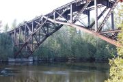
A scenic highlight that is planned although not yet constructed is the
unique Escanaba & Lake Superior Railroad steel center cross braced
arch bridge over Menominee River. That is going to be quite an effort to
construct and will most definitely garner much attention once in place.
While the approaches, piers and the spans are fairly standard, the
center portion of the bridge is very distinctive. Its method of
construction will be as much of interest as will be the actual finished
product.
There is limited scenery and structures currently as most efforts are
going towards insuring sound benchwork and operationally reliable
trackwork. Glenn's primary goal is to have the layout operational and
running well, then to progress on to these other phases.
Lighting is a mix between ceiling mounted fluorescent tubes and dimmable
track lighting. We discussed color and type of bulbs and the vast array
that is now readily available. Before it was the case that you couldn't
find the exact product that you wanted. Now the challenge is deciding
between which of several options that appear to be nearly identical.
While Glenn says the current lighting is working for him, he notes a
transfer to LED seems probable sometime in the future.
Much credit is extended by Glenn to several people in the progress of
his layout to this point. These begin with his wife Mary, and his sister
Terry, in construction of buildings and scenery. Bill Mosteller has been
a major help in the design and construction. Ian Anderson and his
father, Bruce, have also helped in construction of the layout. Jan Clark
has driven up from Fredericksburg to also contribute towards the
construction efforts.
During discussion with Glenn about progress on his layout and future
plans, he made a very familiar comment that I have heard repeated with
other layout open house owners - the pending date spurred some
construction, details and other general work that had been on the 'to
do' list, some for extended lengths of time. So, between some helpful
family and friends, and the desire to have it ready to show, we are
definitely looking forward to future progress updates and opportunities
to visit Glenn's layout in person.
Now the question for you the reader is this: how's the progress coming
along on your layout? Maybe it's time for you to schedule an open house
event sometime in the near future, to set that goal for a specific
milepost you would like to reach!
Photos by Lee Stoermer unless noted