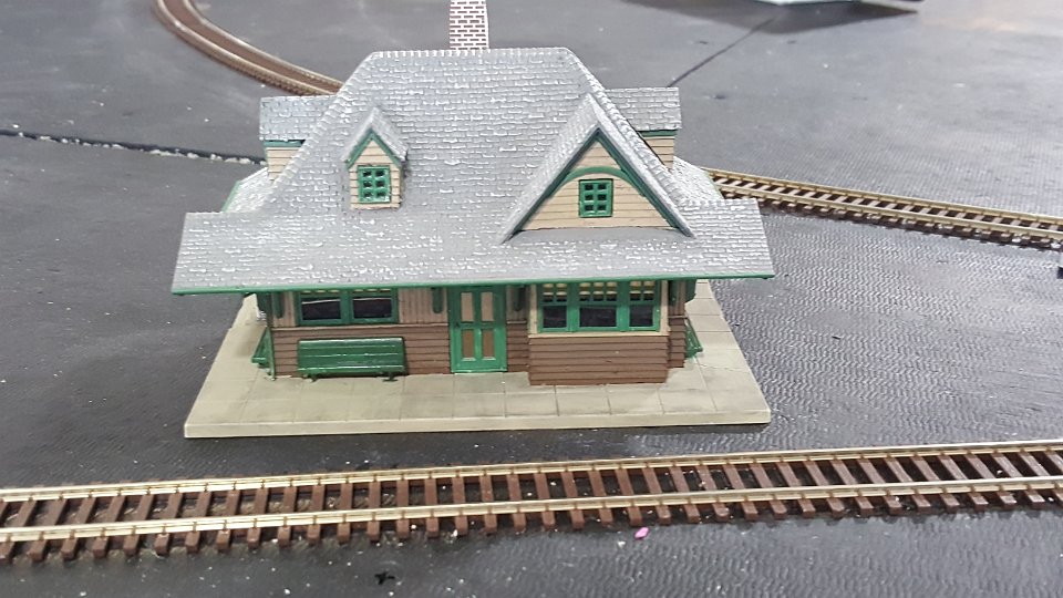
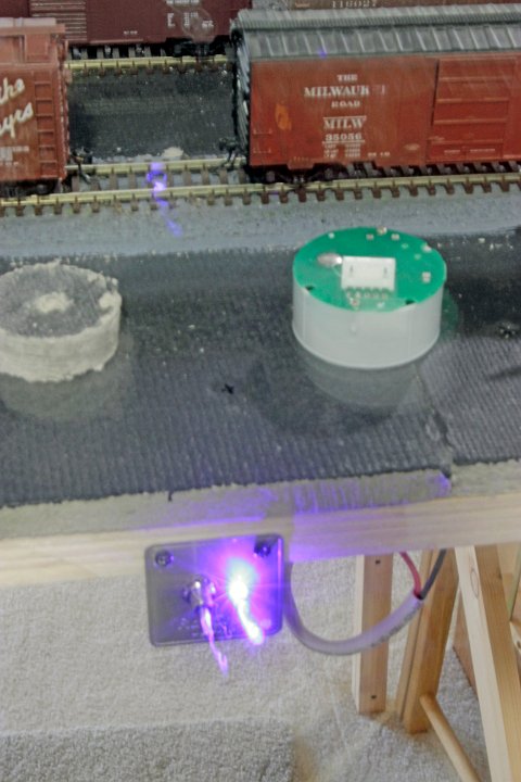
15 John has installed several Rapido Railcrew On-off uncouplers on his layout. The uncoupler is activated by a fascia switch. When on both the fascia panel and the installed coupler show a blue light. The green object on the layout is an uncoupler yet to be installed.
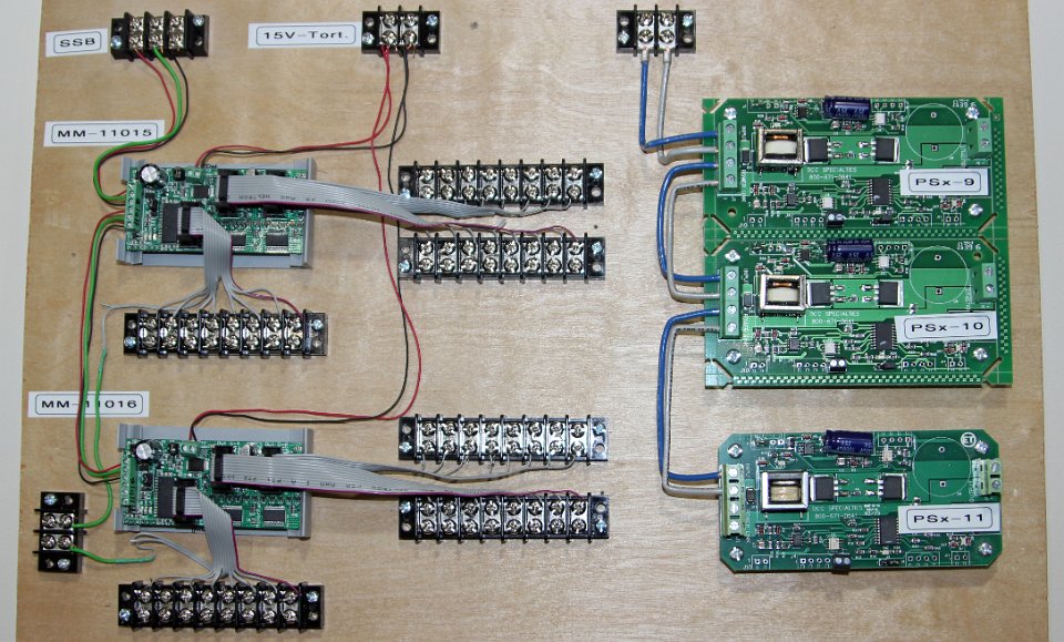
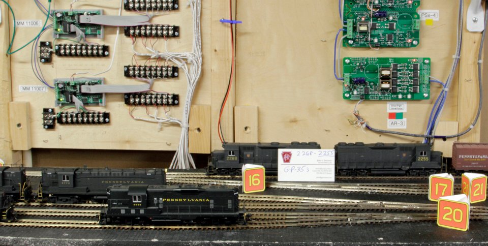
16 Appropriate for a model railroad in Virginia, the power bus is blue and gray wire.
17 Layout power is protected by the DCC Specialties Power Shield devices on the right of this yet to be installed board. On the left are RR-CirKits MotorMan devices which enable control mapping and position recall of all turnouts to JMRI for the panel images operators will use to move turnouts.
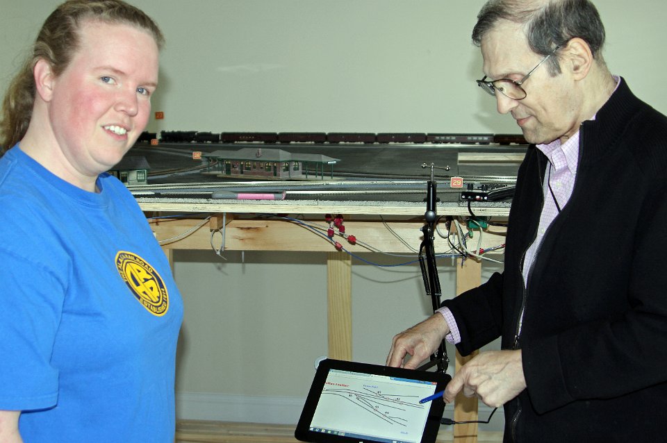
18 Jerry Wolfson is showing Elizabeth Boisvert an Android tablet for the small yard at Cresson.
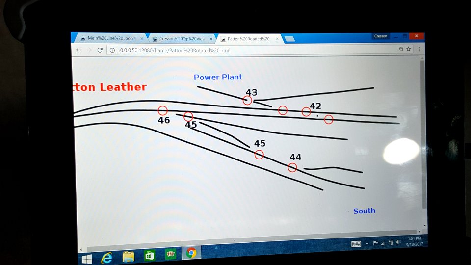
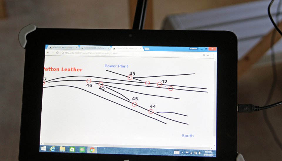
19 In this close-up of a tablet, turnout numbers are shown in their locations on the track plan. Turnouts are switched simply by touching the red circles.
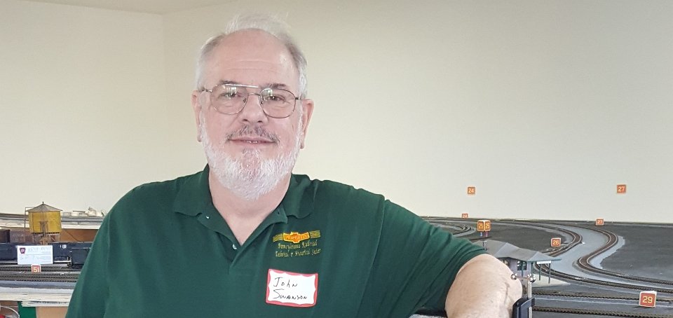
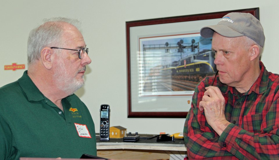
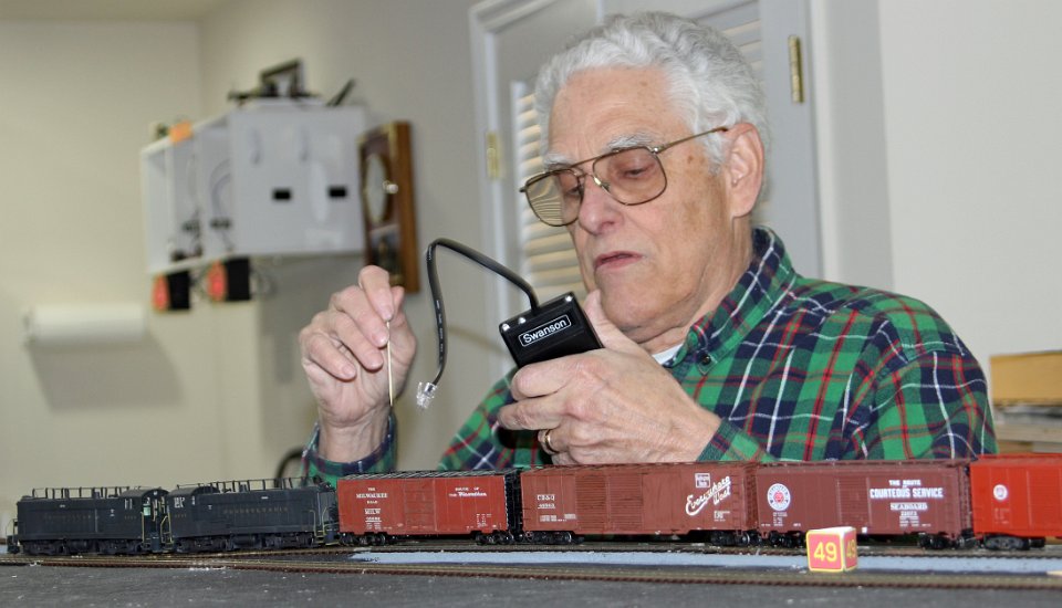
20 John Swanson, on the left, is discussing layout construction with Jerry Skeim.
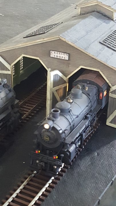
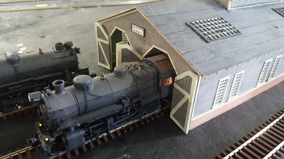
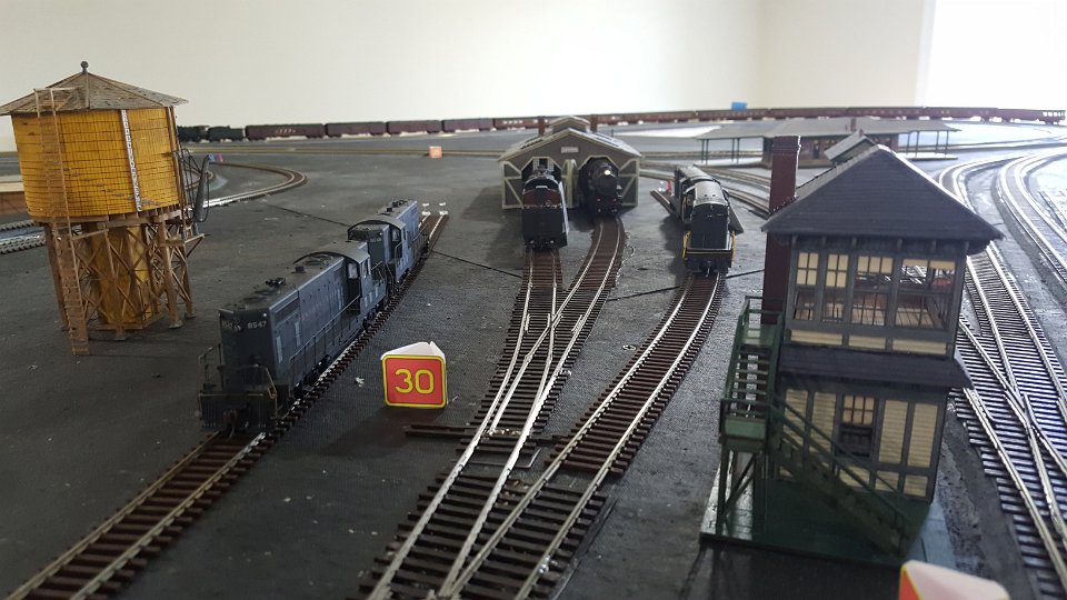
21 This is the engine facility at Altoona, the layouts staging area. John sealed all the Homasote with black paint to prevent warping when he glues down ballast.
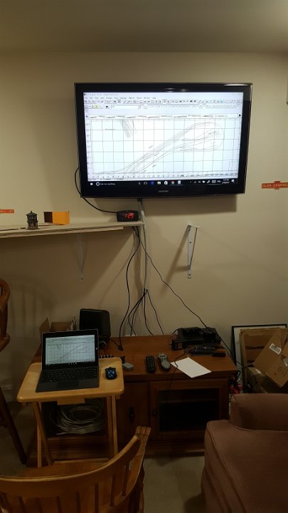
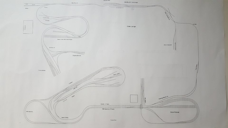
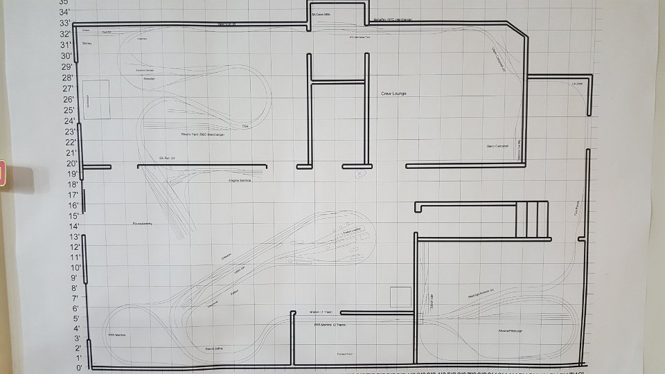
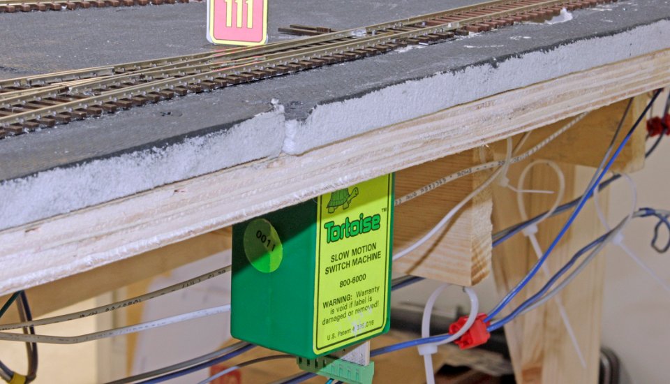
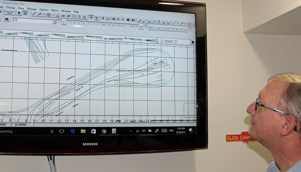
22 Roger Boughton is examining an XTrackCad drawing on a monitor John placed in the crew lounge. John has separate drawings, called layers, for house wiring, bench work, his track plan, layout wiring and other views. Using the joist layer and the track plan layer, John was able to plan joist locations that would not interfere with installing Tortoise switch machines.
23 Doug Kirkpatrick is dialing up an engine. John uses Digitrax radio DCC and has both UR-91 and UR-92 receivers to accommodate his guest operators’ simplex and duplex throttles.